Difference between revisions of "FIRECRACKER V2.0.0.33"
X10douglas (talk | contribs) |
X10douglas (talk | contribs) |
||
| Line 9: | Line 9: | ||
The Firecracker software was originally created as a part of the Firecracker kit (CK18A). Since its inception, the Firecracker Computer Interface (CM17A) has been incorporated into other kits; i.e., MultiView and X-Ray Vision. Due to the modular nature of X10 equipment, the Firecracker application may be utilized as long as specific equipment is available. The following X10 hardware is the minimum equipment required to use the Firecracker application: | The Firecracker software was originally created as a part of the Firecracker kit (CK18A). Since its inception, the Firecracker Computer Interface (CM17A) has been incorporated into other kits; i.e., MultiView and X-Ray Vision. Due to the modular nature of X10 equipment, the Firecracker application may be utilized as long as specific equipment is available. The following X10 hardware is the minimum equipment required to use the Firecracker application: | ||
| − | *(1) Firecracker Computer Interface (CM17A) | + | *(1) Firecracker Computer Interface (CM17A) [[Image:tech_cm17a.jpg]] |
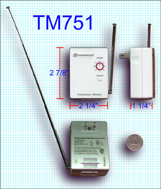
| − | *(1) Transceiver (TM751 or RR501) | + | *(1) Transceiver (TM751 or RR501) [[Image:tech_tm751.jpg]] |
Revision as of 00:28, 15 May 2014
Introduction
The following document covers the features and configuration of the Firecracker software. Firecracker enables your PC to function as a remote control. Once configured, you will be able to control lights, appliances, and cameras from your Windows desktop with a few clicks of the mouse.
Hardware Installation
The Firecracker software was originally created as a part of the Firecracker kit (CK18A). Since its inception, the Firecracker Computer Interface (CM17A) has been incorporated into other kits; i.e., MultiView and X-Ray Vision. Due to the modular nature of X10 equipment, the Firecracker application may be utilized as long as specific equipment is available. The following X10 hardware is the minimum equipment required to use the Firecracker application:
- (1) Firecracker Computer Interface (CM17A)

- (1) Transceiver (TM751 or RR501)


Configuring the Firecracker Computer Interface
- Connect the female DB9 connector on the Firecracker Interface directly to your PC's serial port.
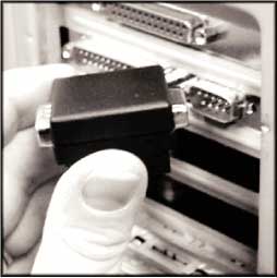
- If you own an MR26A PC Receiver, it can be connected to the male DB9 connector (pass-through port) on the Firecracker Interface.
- If the computer's case or other cables prevent the Firecracker Interface from connecting properly, you may have to purchase an extension serial cable from a local computer parts supplier.

Note: You may connect other serial devices to the pass-through port of the Firecracker Interface; however, if the device operates all the time (mouse, modem, etc.), the Firecracker Interface will not operate properly. A device operating at all times should be connected to its own serial port.
Configuring The Transceiver
- Set the House dial on the face of the unit to "A."
- Temporarily plug an incandescent lamp into the outlet on the bottom of the Transceiver (first make sure the lamp's power switch is ON).
- Plug the Transceiver into an AC outlet.
- Press the ON/OFF button on the face of the unit. You should hear the relay inside click, and the lamp will turn on or off. This verifies that the Transceiver is connected to power and is ready to send and receive commands.
- Press the ON/OFF button again until the relay (and the lamp) is off.
- Extend the Transceiver's antenna.
Note: The TM751 Transceiver does not have a Unit dial. It is preset to Unit code 1.
Software Installation
Installation of the Firecracker software is easy. Download the installation file from the X10 web site (www.x10.com/software). Shut down all other programs currently running on your computer. Double click on the Firecracker installation file. Throughout the installation process, you will see the following windows:
![]() Welcome Window
Welcome Window
Click Next to continue with the installation or Exit to abort.

![]() Destination Directory
Destination Directory
If you wish to change the directory where the Firecracker application files will be saved, navigate to the new location. When the new directory has been selected, or the default directory will be used, click Next to continue.

![]() File Transfer
File Transfer

A few moments to transfer the files...
![]() Installation Complete
Installation Complete
...and you are finished! Click OK to exit the installation. Restart Windows.

Graphical User Interface
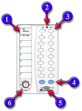
The main Firecracker Graphical User Interface is a representation of the PalmPad Remote (HR12A). This section will explain the various parts and functions of the User Interface.

![]() Module Labels
Module Labels
This section displays a short name representing the House/Unit code of a device controlled by an X10 module. You can configure the labels including the size and type of font. In the upper left corner of each label is the Unit code. The number displayed for each row will change if the Unit Selection Switch at the bottom of the User Interface is toggled.
![]() Transmit LED
Transmit LED
Any time the ON, OFF, DIM, or BRIGHTEN buttons are pressed, the red LED at the top of the User Interface will flash (pulsate) to indicate transmission of the command.
![]() Control Buttons
Control Buttons
These buttons allow you to transmit ON and OFF commands for specific units assigned to the House code currently set on the House code dial.
![]() Dim / Bright Control Buttons
Dim / Bright Control Buttons
These light blue buttons control the dimming and brightening functions for Lamp Modules and Wall Switch Modules. The left button (UP arrow) controls brightening and the right button (DOWN arrow) controls dimming. When these buttons are used, the command is sent to the last House/Unit code used. These buttons may be pressed once to change the light level by one step or they may be held down to send repeated commands and released when the desired level is achieved.
![]() Unit Selection Switch
Unit Selection Switch
This switch controls the assignment of the ON and OFF Control Buttons and the displayed Module Labels above. If the switch is set to the left (1-8), the Control Buttons are set to Units 1 through 8 and the Module Labels display 1 through 8. If the switch is set to the right (9-16), the Control Buttons are set to Units 9 through 16 and the Module Labels display 9 through 16.
![]() House Code Dial
House Code Dial
This dial represents the House code the Firecracker will transmit if any of the Control Buttons are clicked. If Module Labels have been assigned over more than one House code, the labels displayed will change as each House code is selected
Pop-Up Menu
To access the pop-up menu, right mouse click anywhere on the User Interface. If you right mouse click over the Module Labels, the Unit Selection Switch, or the House Code Dial, the pop-up menu will have an additional option corresponding to the section the mouse pointer is over when the right mouse button is pressed.

About Firecracker
Select this command to view the About dialog box, which lists the software version. The dialog box also contains an Upgrade button, which launches your browser and takes you to the X10 website.
Help Select this command to view the online help file.
Print Labels This menu command allows you to print your Module Labels. The labels can be cut out and placed under the plastic label cover of any HR12A PalmPad remotes you own.
Sounds Select this menu command to enable or disable sounds corresponding to actions occurring in Firecracker.
Setup Firecracker

Use this menu command to select the serial port to which the Firecracker Interface is connected. The Firecracker Interface is used with other X10 programs (i.e. MultiView) and can be used in conjunction with our MR26A PC Receiver (also known as the Firecracker Receiver).
If you do not know to which comport the Firecracker Interface is connected, select the Automatic radio button in the Firecracker Transmitter section. It is important that all other programs, which may be utilizing your comports, be shut down during setup of the Firecracker software. If you know which comport to use, select the Manual, Use This Serial Port radio button and then the appropriate comport from the selection box.
To test the Firecracker Interface, click on the Send Test Command button (default command is A1 ON). To change the test command, click on the Edit Test Command button.
The Firecracker Receiver section of the dialog box pertains to the configuration of the MR26A PC Receiver. If you do not have an MR26A connected to your computer, select the Disabled, No Receiver radio button. The Received Commands box will display any commands sent by remote controls or motion detectors (PalmPads, HawkEyes, etc.). The commands will be displayed as A1 ON, C7 OFF, etc.
View Command History Select this option to open a dialog box that displays the history of commands sent by the application.
Display Select this submenu to choose from three styles of User Interfaces: PalmPad, DigiPad, or SlimFire.
Task Bar Icon Select this submenu to choose from four styles of System Tray icons: PalmPad, DigiPad, X10, or Firecracker.
Startup Menu Select this submenu to choose to add or remove Firecracker from your Startup menu.
Move Select this menu command to engage the move mode. The mouse pointer will change to a hand. Click and drag anywhere on the User Interface. Drag the image to a new location on the screen. Release the mouse button when the new location has been reached.
The User Interface can also be moved by clicking and dragging anywhere on the User Interface except for the Module Label area, the House Code dial, the Unit Selection Switch, and the Control Buttons.
Minimize
This menu option will minimize the User Interface. A Taskbar button for Firecracker will not be displayed. Firecracker places a System Tray icon on your Taskbar. Click on the System Tray icon and then select Restore to return the User Interface to its original screen position.
The User Interface may also be minimized by pressing the Escape key.
To restore the User Interface, double click on the Firecracker's icon in the System Tray on the taskbar.
Original Size
This menu option will return the User Interface to its original size if it has been resized. Use this option if the User Interface does not redraw properly after a window covering it is moved.
www.x10.com This menu command will launch your browser and direct it to the X10 web site.
Close This menu command will cause Firecracker to ask if you wish to close the application. You may choose Yes, No, or Minimize.
Configuring The Software
This section covers establishing communication between the Firecracker Interface and the Transceiver, as well as configuring the User Interface to your liking.
Configuring And Testing The Firecracker Application
- Before loading Firecracker, shut down any programs that utilize a communications port (comport) to avoid any possible conflicts during the configuration process (i.e. PDA or digital camera software).
- Run the Firecracker application (Start button | Programs | Firecracker | Firecracker).
- A graphic of the PalmPad appears. This is the User Interface.
- Right mouse click on the User Interface to engage the pop-up menu.
- Select Setup Firecracker.
- A warning dialog box appears. Click OK to continue.
- The Setup Firecracker dialog box appears.
- If you do not know to which comport the Firecracker Interface is connected select the Automatic radio button in the Firecracker Transmitter section.
- If you do know to which comport the Firecracker Interface is connected select the Manual radio button and then the comport from the selection box.
- If you do not have an MR26A PC Receiver (also known as the Firecracker Receiver) connected to your computer select the Disabled radio button in the Firecracker Receiver section.
- If you do own an MR26A, which has already been configured for use with other X10 software (i.e. MultiView), leave the Firecracker Receiver setting as it is. The Firecracker application does not utilize the MR26A.
- Click on the OK button to save your settings and return to the User Interface.
- The House Code dial in the lower left corner of the User Interface is set to "A" by default. If it has been changed, set it back by clicking on the "A." Note: The dial displays the odd letters (A, C, E, etc.). The small ticks between these letters represent the even letters (B, D, F, etc.).
- An alternate method to changing the House code is to right mouse click on the House Code dial to engage the pop-up menu. Select the House Code... menu option and then "A."
- The Unit Selection Switch is located in the lower right corner of the User Interface. Clicking on the switch causes it to move from the 1-8 position to the 9-16 position or vice versa.
- Verify the switch is in the 1-8 position. Change it if necessary.
- The Transceiver has been configured to A1. To turn it on, click on the ON button in the row next to the Module Label "My Appliance" (top row) on the User Interface.
- The red LED at the top of the User Interface will flash briefly. The Firecracker application has sent the A1 ON command to the Firecracker Interface, which has transmitted the command to the Transceiver.
- You should hear the relay inside the Transceiver click on. This confirms that the Firecracker Interface is transmitting properly and the Transceiver is receiving and responding to commands. If you do not hear the click, press the OFF button on the User Interface instead. The Transceiver's relay may already be in the ON position. If you still have a lamp plugged into the Transceiver, it should turn on or off as you send the commands.
- If you have other Lamp, Appliance, or Wall Switch Modules configure them and then use the Firecracker application to test their control.
Configuring The Module Labels
- To change a module label's text, double click in the module label's text area.
- A dialog box will appear. Enter the new name for the label.
- To change the font type or size, click on the Font button.
- Another dialog box appears. Select the new attributes you wish to apply to the text.
- Click the OK button to see the sample text in the previous dialog box. Experiment with the settings until the desired look is achieved.
- When all changes to the Module Label are complete, click the OK button to return to the User Interface.
- To save the changes, right mouse click to enable the pop-up menu.
- Chose the Close menu command.
- A dialog box appears asking if you wish to close the application. Select the Yes button.
- The Firecracker application shuts down. The changes have been saved.
Printing The Module Labels
The Print Labels command allows you to print a label insert that fits into any HR12A PalmPad remote.
- Right mouse click on the User Interface to engage the pop-up menu.
- Select Print Labels.
- To print all House codes, click the All radio button.
- To print specific House codes, click the Selected radio button and then check the desired House codes in the selection box.
- If the printer settings need to be changed, click the Setup button.
- To see what the printout will look like, click the Print Preview button.
- When all changes to the settings are complete, click the Print button.
- The Print dialog appears. Click the OK button.
- The label inserts are printed.
- The Print dialog disappears. Click the Cancel button in the Print Labels dialog box to return to the User Interface.
Using Keyboard Commands
To turn a module ON or OFF:
- Type the House code (A through P).
- Type the unit code (1 through 16).
- Type the letter N for ON and F for OFF.
To dim or brighten a lamp module:
- Type the house code (A through P).
- Type the unit code (1 through 16).
- Press the + (plus) key to brighten and the - (minus) key to dim.
- For repeated dimming or brightening of the same module, you can press + (plus) or - (minus) without entering the House or Unit code again.
To delete the last entry press the Delet or Backspace key.
To cancel the last command press the Escape key.
Frequently Asked Questions
For frequently asked questions, please click here.