Difference between revisions of "VT37A"
Jump to navigation
Jump to search
| Line 8: | Line 8: | ||
;Power Supply: 12VDC, 150mA & 5.5VDC, 500mA | ;Power Supply: 12VDC, 150mA & 5.5VDC, 500mA | ||
;Transmission Range: 100ft. | ;Transmission Range: 100ft. | ||
| − | + | ===SETUP=== | |
| + | #Connect the jack on the audio cable (supplied) to the speaker/headphone jack, or line out jack on your PC’s sound card. Use adapter if needed. | ||
| + | #Connect the red RCA plug to the jack labelled AUDIO RIGHT and the white RCA plug to the jack labeled AUDIO LEFT on the Photo Sender. | ||
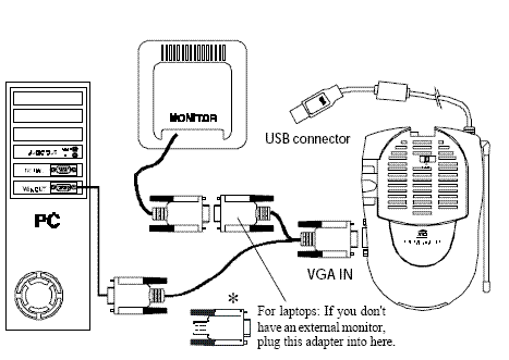
| + | #Connect the VGA cables as shown below so that the VGA out from your PC connects to the VGA input on the VT37A Photo Sender and then also passes to the VGA input on your monitor. Note * for laptops. | ||
| + | #Set the channel switch (on the TOP of the unit) to channel A (to the RIGHT). | ||
| + | #Plug the Photo Sender’s Power Supply into a convenient 120 volt wall outlet and plug its jack into the Photo Sender. | ||
| + | #Turn the power switch (on the side of unit) on. | ||
| + | #Position the Photo Sender in a convenient location and orient the antenna so that the flat side points in the direction of the room where you will be installing the Receiver. | ||
[[Image:Vt37ahookup.GIF]] | [[Image:Vt37ahookup.GIF]] | ||
Revision as of 21:24, 14 April 2008
VT37A
TRANSMITTER, SHOWTIME
SPECIFICATIONS
- FCC ID
- B4SVT37A
- Power Supply
- 12VDC, 150mA & 5.5VDC, 500mA
- Transmission Range
- 100ft.
SETUP
- Connect the jack on the audio cable (supplied) to the speaker/headphone jack, or line out jack on your PC’s sound card. Use adapter if needed.
- Connect the red RCA plug to the jack labelled AUDIO RIGHT and the white RCA plug to the jack labeled AUDIO LEFT on the Photo Sender.
- Connect the VGA cables as shown below so that the VGA out from your PC connects to the VGA input on the VT37A Photo Sender and then also passes to the VGA input on your monitor. Note * for laptops.
- Set the channel switch (on the TOP of the unit) to channel A (to the RIGHT).
- Plug the Photo Sender’s Power Supply into a convenient 120 volt wall outlet and plug its jack into the Photo Sender.
- Turn the power switch (on the side of unit) on.
- Position the Photo Sender in a convenient location and orient the antenna so that the flat side points in the direction of the room where you will be installing the Receiver.
SPECIAL NOTE
The VT37A does not require X10 software to transmit video to an X10 video receiver using the VGA connection. Software, like Showtime, is required to connect the USB cable in order to control the PC with an X10 remote from the TV`s location. However, this is not necessary to send audio and video- you can play video in your favorite media player and watch the output on your TV.

